hyperDENT V9.1
Freedom through innovation
Our development team has been working continuously on a variety of new functions and improvements which have been included in the new hyperDENT Version 9.1. The primary goal was to significantly accelerate your workflow. In addition to numerous enhancements and improvements to standard functions, you will find many new and revised automation options in the new version V9.1. These will help speed up internal workflows thereby saving time and money.
That’s how to make work more fun!
|
Simplified Workflow |
|---|
Compact NEW User Interface
Visual and functional improvements to the user interface make working with hyperDENT Compact NEW even more intuitive. If connectors are missing, you will be notified by a blinking button. Available functions for the specific work process are found directly in the respective work area and non-applicable buttons are hidden or greyed out making your user environment more clearly structured and easy to use.

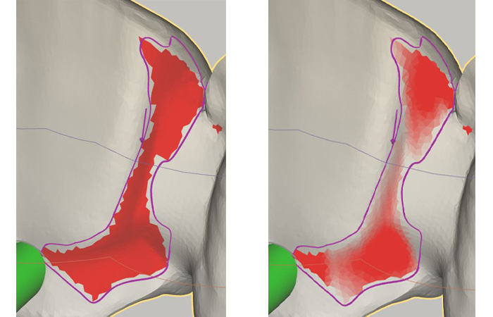
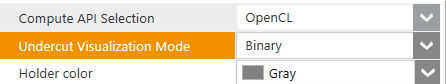
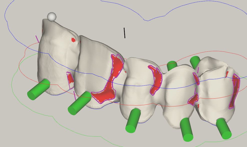
Visualisation of Undercut Areas
The visualization of the undercuts generated by connectors has been significantly improved and positioning performance greatly increased using state-of-the-art Open CL technology. For the visual display of the undercuts, you can choose between “smooth” and “binary”. The advantage of this is that especially critical areas can be identified more easily based on the degree of coloration.
Connectors
Editing and displaying connectors have been greatly improved and expanded in various application areas. Decide for yourself if the connector profile or user-defined settings should be applied. After importing the parts, the connectors will be generated automatically according to your settings. Editing all or individual connectors has been simplified with a separate button in hyperDENT Compact NEW.
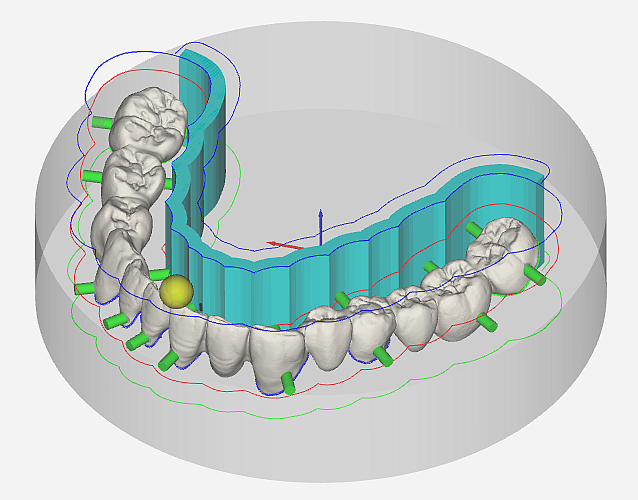
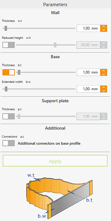
Creation of Sintering Frames
Newly available parameters will make the creation of different frame types child’s play.
The height of the sintering frame can be easily adjusted using hyperDENT Version 9.1. A reduction of the frame height shortens the manufacturing process while increasing process reliability. The adjustment to the reduced frame height occurs automatically using the sintering pin. Via a new job, both can be generated with the exact same height. This simplifies the coloration of dental restorations and reduces the time required for manual grinding of sintering pins.
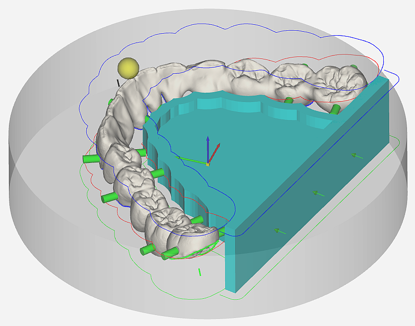
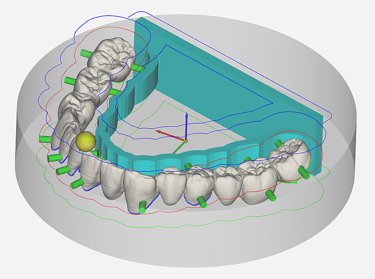
Increased stability during the positioning of bridge frameworks on the edge of circular blanks (for open fixtures) can be achieved using additional connectors on the base of the sintering frame. Since almost no connectors are then needed in the front section, the process time is radically reduced.
Performance
You can now enjoy even higher performance throughout the production process. We have further optimized the performance of various processes so that project loading time, simultaneous deletion of multiple parts and modification of templates can all be done much more quickly.

| Automatisms |
|---|
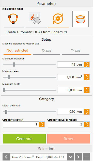
Automatic Generation of User Defined Areas
A separate icon now enables user defined areas to be created and edited more efficiently. The fully automatic recognition of user defined areas for undercuts allows significantly quicker generation of optimal tool paths. Optimal angles for user defined areas are also now recognized and executed. The machine axis limits are thereby considered resulting in reduced milling time.
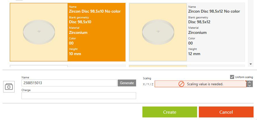
Blank Management
Additional parameters have been added to the blank management area and the visual design has been improved. There are new options for grouping and sorting projects and blanks according to specific criteria. Blank names can now be generated automatically based on various settings providing a better overview and enabling you to find the appropriate blank in the database more quickly.
| Tool Path Generation and Management |
|---|
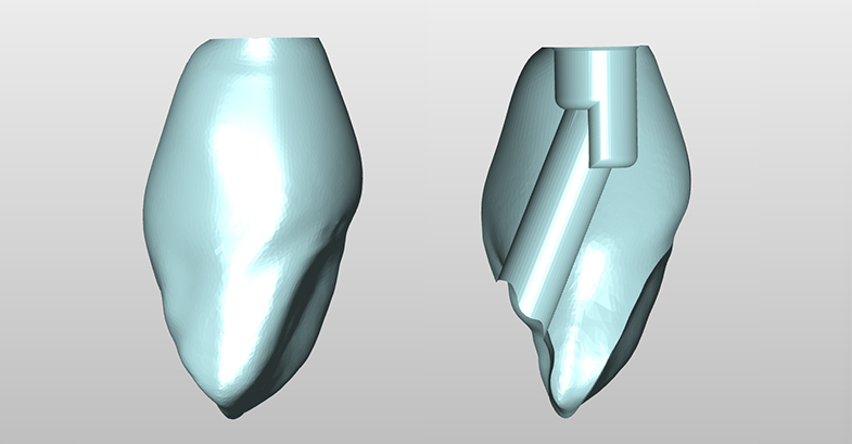
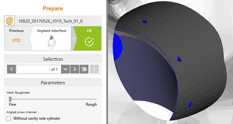
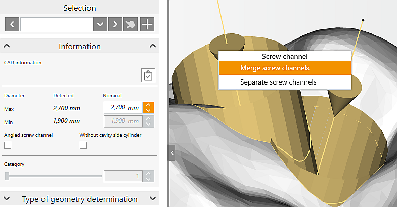
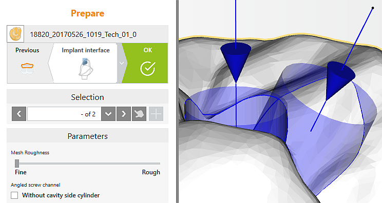
Processing Angled Screw Channels
Additional improvements have been added to hyperDENT for the recognition and processing of angled screw channels. The metadata provided by the CAD system is now more thoroughly interpreted so that even extreme cases can be handled easily using the new hyperDENT mechanisms. Furthermore, whether the channel is broken or simply runs diagonally to the implant axis is determined automatically for angled screw channels. If the processing end is set to End/Begin Angulation in the screw channel process, this will automatically be set to End Screw Channel for diagonal screw channels.
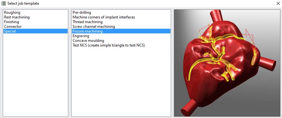
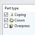
Processing Fissures
In addition to the anatomic part types such as crowns, you can now process fissures for non-anatomic restorations (i.e. caps). This reduces the number of required templates drastically.
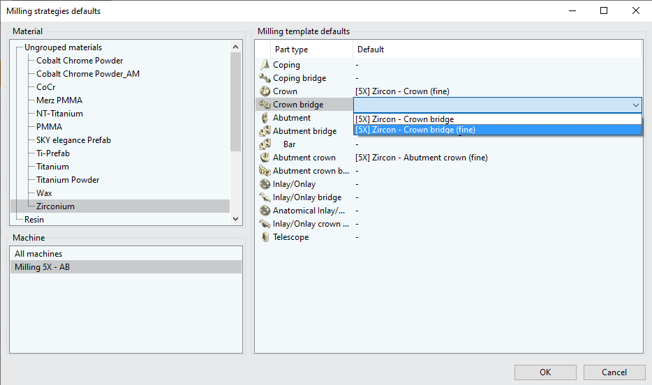
Defining Default Templates
In hyperDENT Compact NEW, it is now possible to assign default templates for specific restoration types without an additional template editor license. By assigning a standard template, the manual selection of the desired template can be omitted making your workflow more efficient.
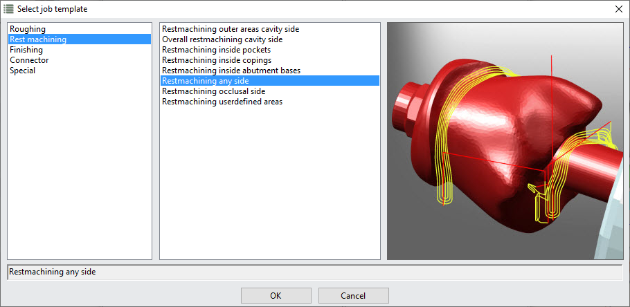
Restmachining Any Side
Residual material can be removed from any direction using the new “Restmachining Any Side” function. Part quality is thereby increased while processing time is decreased.
Optimization of Milling Cycles for 4 and 5 Axis Machines
A reduction in calculation and processing time has been achieved through the optimization of the milling strategies for 4 and 5 axis machines. The impressive result is smoother tool paths and improved undercut strategies.
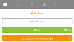
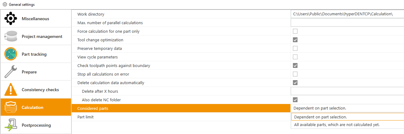
Expanded Calculation Settings
Using the expanded calculation settings, you can select whether only the selected STL models or all parts nested in the blank should be calculated.
| Hybrid/Additive Manufacturing |
|---|
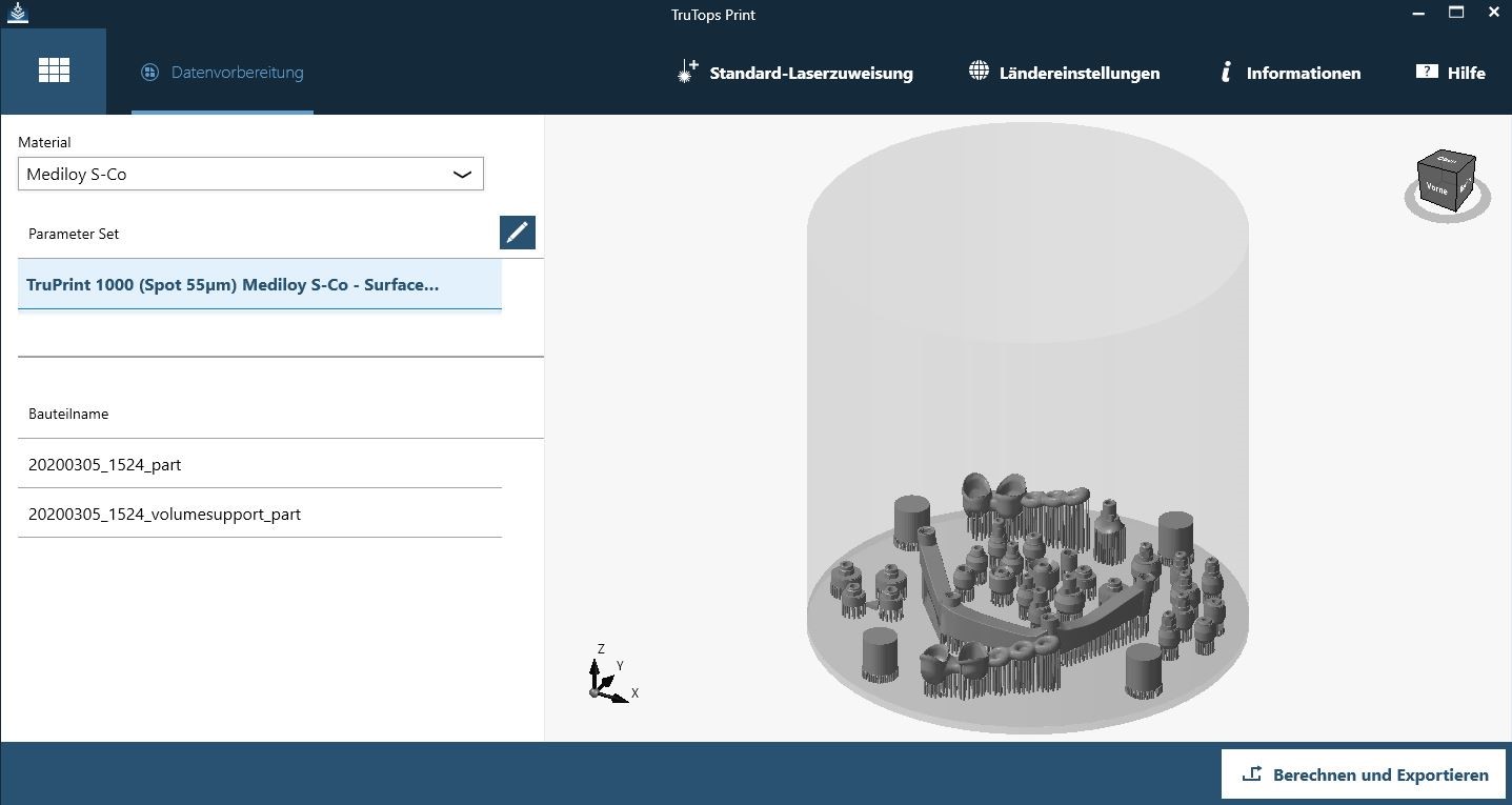
Trumpf Interface
hyperDENT now supports the WZA output format for Trumpf laser sintering machines. Via the direct interface to the Buildprozessor*, the building platform can be converted to the desired slice format with the touch of a button.
* The Buildprozessor is not a FOLLOW-ME! product
| Chairside Solution |
|---|
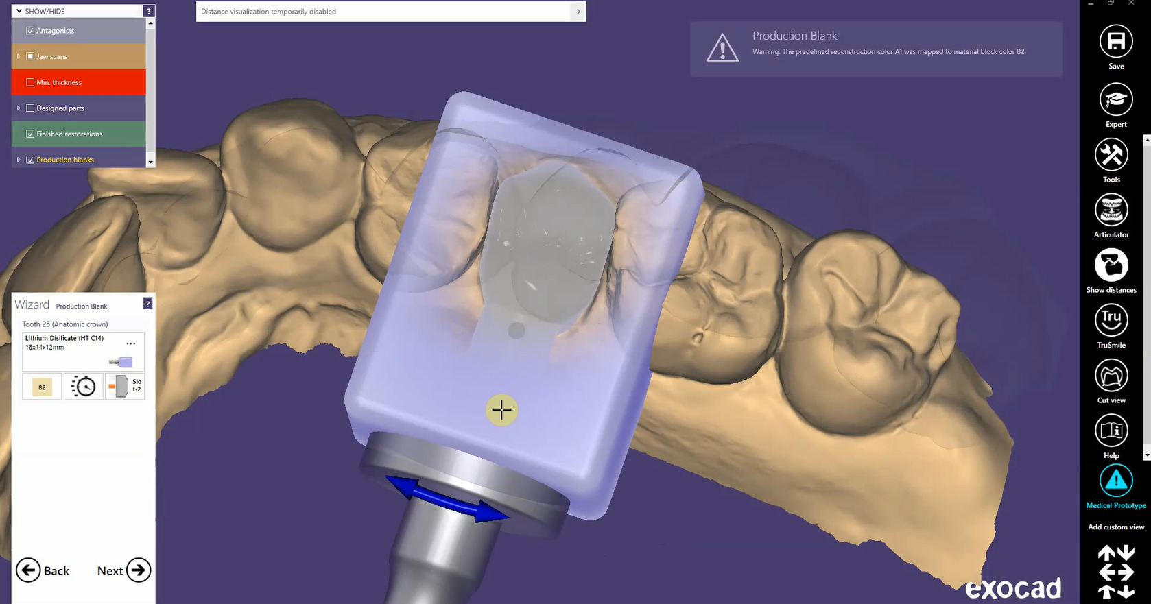
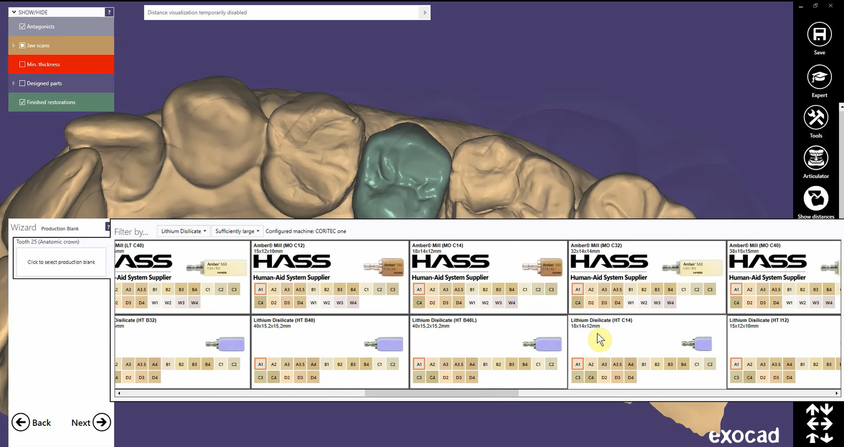
Exocad Chairside Solution
hyperDENT has been fully integrated into exocad. The new Chairside Workflow enables the entire workflow to be visualized in the exocad user interface.